

Modbus, a well - known communication protocol, has been widely used in the industrial automation field for decades. As a general PLC (Programmable Logic Controller) supplier, we have in - depth knowledge and rich experience in integrating Modbus and other communication protocols into our PLC products. In this blog, we will explore how to use communication protocols like Modbus in a general PLC, providing you with a comprehensive guide to enhance your industrial control system's efficiency and connectivity.
Understanding Modbus Protocol
Modbus is an open - standard communication protocol developed by Modicon (now Schneider Electric) in 1979. It is a master - slave protocol, which means there is one master device that initiates communication requests, and multiple slave devices that respond to these requests. Modbus supports different transmission modes, including Modbus RTU (Remote Terminal Unit), Modbus ASCII, and Modbus TCP/IP.
Modbus RTU is the most commonly used mode in industrial applications. It uses a binary encoding format, which is more efficient in data transmission compared to Modbus ASCII. Modbus TCP/IP, on the other hand, is designed for Ethernet - based networks, enabling seamless integration with modern industrial Ethernet infrastructure.
Prerequisites for Using Modbus in a PLC
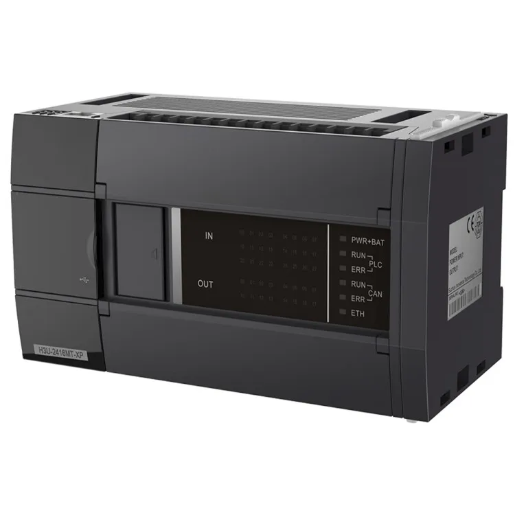
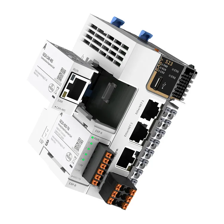
Before implementing Modbus in a general PLC, several prerequisites need to be met. First, your PLC should support the Modbus protocol. Most of our general PLCs, including CAN Bus PLC, EtherCAT Bus PLC, and Compact Mini PLC, are equipped with Modbus - compatible communication interfaces.
Secondly, you need to understand the hardware connections. For Modbus RTU, a serial communication interface (such as RS - 485) is required. The master and slave devices should be connected in a multi - drop network, where all slaves share the same communication line. For Modbus TCP/IP, an Ethernet connection is necessary, and the devices should be configured on the same network.
Configuration Steps
1. PLC Configuration
The first step is to configure the PLC to act as either a Modbus master or a slave. If your PLC is the master device, it will be responsible for sending read or write requests to the slave devices. In our PLC programming software, you can easily set the communication parameters, such as the baud rate, parity, and stop bits for Modbus RTU, or the IP address and port number for Modbus TCP/IP.
For example, if you are using our Compact Mini PLC as a Modbus master, you need to open the programming software, select the communication module, and enter the appropriate Modbus settings. The software will guide you through the process, ensuring that the configuration is accurate.
2. Slave Device Configuration
Each slave device in the Modbus network has a unique slave address. You need to configure the slave address for each device according to the network requirements. In addition, you should also define the data registers and coils that the master can access.
For instance, a temperature sensor acting as a Modbus slave may have a specific register address that stores the temperature value. The master PLC can then read this register to obtain the temperature information.
3. Data Mapping
Data mapping is a crucial step in using Modbus in a PLC. You need to map the data registers and coils in the Modbus network to the internal memory of the PLC. This allows the PLC to process the data received from the slave devices and perform the necessary control actions.
In our PLC programming environment, you can create a data mapping table. For example, if the slave device's register 0x0001 stores the speed value of a motor, you can map this register to a specific memory location in the PLC. Then, the PLC can use this value to control the motor speed.
Programming the PLC for Modbus Communication
Once the configuration is complete, you can start programming the PLC to communicate with the Modbus devices. Here are the common programming steps:
1. Initializing the Communication
In the PLC program, you need to initialize the Modbus communication interface. This includes setting the communication parameters, opening the communication port, and establishing the connection with the slave devices.
// Example code for initializing Modbus RTU communication in our PLC
PROGRAM Modbus_Init
VAR
    Modbus_Handle: INT;
    BaudRate: INT := 9600;
    Parity: INT := 0; // No parity
    StopBits: INT := 1;
BEGIN
    Modbus_Handle := Modbus_RTU_Open('COM1', BaudRate, Parity, StopBits);
    IF Modbus_Handle > 0 THEN
        // Communication initialized successfully
    ELSE
        // Error handling
    END_IF;
END_PROGRAM
2. Sending Read and Write Requests
To read data from a slave device, the master PLC sends a read request to the specific slave address and register range. To write data to a slave device, a write request is sent with the appropriate data value.
// Example code for reading data from a Modbus slave
PROGRAM Modbus_Read
VAR
    Modbus_Handle: INT;
    SlaveAddress: INT := 1;
    StartRegister: INT := 0;
    NumRegisters: INT := 10;
    DataBuffer: ARRAY[0..9] OF INT;
    Result: INT;
BEGIN
    Result := Modbus_RTU_ReadHoldingRegisters(Modbus_Handle, SlaveAddress, StartRegister, NumRegisters, DataBuffer);
    IF Result = 0 THEN
        // Data read successfully
    ELSE
        // Error handling
    END_IF;
END_PROGRAM
3. Error Handling
Error handling is an important part of Modbus communication programming. Errors can occur due to various reasons, such as communication line interference, incorrect slave addresses, or device malfunctions.
In the PLC program, you should check the return values of the Modbus functions. If an error occurs, appropriate actions can be taken, such as retrying the communication, sending an alarm signal, or logging the error information.
Troubleshooting Modbus Communication
Even with proper configuration and programming, Modbus communication issues may still arise. Here are some common problems and their solutions:
1. No Communication
If there is no communication between the master and slave devices, first check the hardware connections. Make sure the cables are properly connected, and the power supply is stable. Also, verify the communication parameters, such as the baud rate, parity, and slave address.
2. Data Inconsistency
Data inconsistency may occur if the data mapping is incorrect or if there is a problem with the data transfer. Check the data mapping table in the PLC program and ensure that the data types and register addresses match between the master and slave devices.
3. Communication Errors
Communication errors can be caused by electromagnetic interference, network congestion, or device failures. Try to isolate the source of the interference, optimize the network configuration, or replace the faulty devices.
Other Communication Protocols and Their Integration
While Modbus is a popular choice, there are other communication protocols that can be used in a general PLC. For example, CAN (Controller Area Network) bus is known for its high - speed and reliable communication, especially in automotive and industrial control applications. Our CAN Bus PLC can support both CAN and Modbus protocols, allowing for flexible integration in different systems.
EtherCAT (Ethernet for Control Automation Technology) is another high - performance protocol that provides real - time communication capabilities. Our EtherCAT Bus PLC can be configured to communicate with EtherCAT devices as well as Modbus devices, enabling seamless integration of different types of industrial equipment.
Conclusion
Using communication protocols like Modbus in a general PLC can significantly enhance the connectivity and functionality of your industrial control system. By following the steps outlined in this blog, you can successfully configure, program, and troubleshoot Modbus communication in your PLC.
As a general PLC supplier, we are committed to providing high - quality PLC products and comprehensive technical support. Whether you need a CAN Bus PLC, EtherCAT Bus PLC, or Compact Mini PLC, we have the right solution for your application. If you are interested in our products or need further assistance in integrating communication protocols into your PLC system, please feel free to contact us for procurement and technical consultation.
References
- Modbus Organization. Modbus Application Protocol Specification V1.1b3.
- PLC Programming Manuals. Our company's official PLC programming documentation.
- Industrial Communication Handbook. Various industry - standard handbooks on industrial communication protocols.